The Mission 771 & 772 amplifier system
This was the first ever Mission amplifier which I designed after starting up the company with Farad Azima. It entered production in 1980 and led to subsequent amplifier models including the die-cast fronted 776-777 models and then the Cyrus amplifiers.This amplifier system was built like a battleship with thick solid aluminium cases made from machined slabs with an absence of visible screws. The 771 Control unit was very unusual in design and was built around complex discrete operational amplifier circuit blocks. The 772 power amplifier was a development of the Lecson AP4 Class A power amplifier but with a Class AB output stage based around three cascode pairs of MJ4502/MJ802 power transistors. This was a dual monobloc with each channel having a huge power supply comprising a Holden & Fisher toriodal transformer and a pair of large Sprague computer grade capacitors. As I recall this amplifier was good for about 160 watts per channel into 8 ohms and something like 250 watts per channel into 4 ohms.This product was launched at the Harrogate Audio Fair where the prototype featured a novel feedback system which largely mittigated the effects of the loudspeaker cables. A third cable was wired to the loudspeaker terminals and fed back a signal to the amplifier. It was easy to hear it working but the idea was dropped for production as being "too complex" for the average buyer of the time.
The control functions of the 771 were quite unusual. From the left the input selector switched between Moving Coil, Moving Magnet, two Aux inputs and two tape inputs. The next two control switches were very radical being low frequency and high frequency bandwidth controls. The three positions selected different settings which controlled the overall frequency response of the system. The row of toggle switches switched two Tape positions; Stereo-Mono; three loudspeaker outputs (switched by relays inside the power amp., dc or ac signal coupling and a gain switch which could reduce the gain by 10 dB or 20 dB ensuring that the Volume control always operated in its most linear range. The switches were followed by a Balance control for each channel offering a +/- 3 dB range and finally there was the big Volume control.
smThe first review of these amplifiers was in the long-gone "Practical Hi-Fi" magazine which featured a photograph on the front cover with the caption "The best sounding amplifier in the world". I guess that says it all.
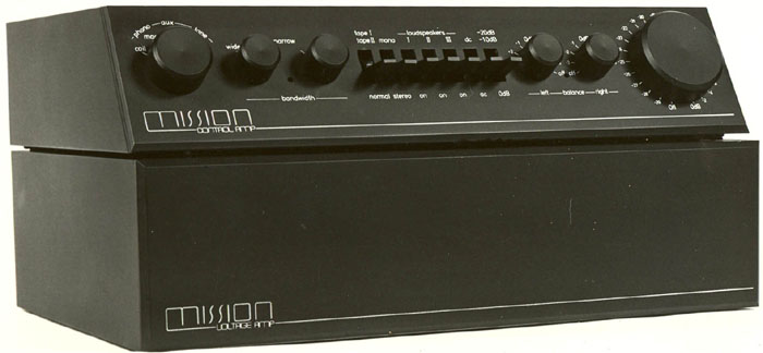 A mass of solid aluminium and no ugly screw heads to spoil the lines A mass of solid aluminium and no ugly screw heads to spoil the lines
 Plenty of loading options for the pickup cartridges and three sets of speaker terminals. The huge power supplies could draw a lot of current so the usual power fuse was replaced by a big contact breaker (above the power cable). The loudspeaker relays were switched from the 771 Control Unit but could also be switched by the three slider switches when the power amplifer was used on its own. Plenty of loading options for the pickup cartridges and three sets of speaker terminals. The huge power supplies could draw a lot of current so the usual power fuse was replaced by a big contact breaker (above the power cable). The loudspeaker relays were switched from the 771 Control Unit but could also be switched by the three slider switches when the power amplifer was used on its own.
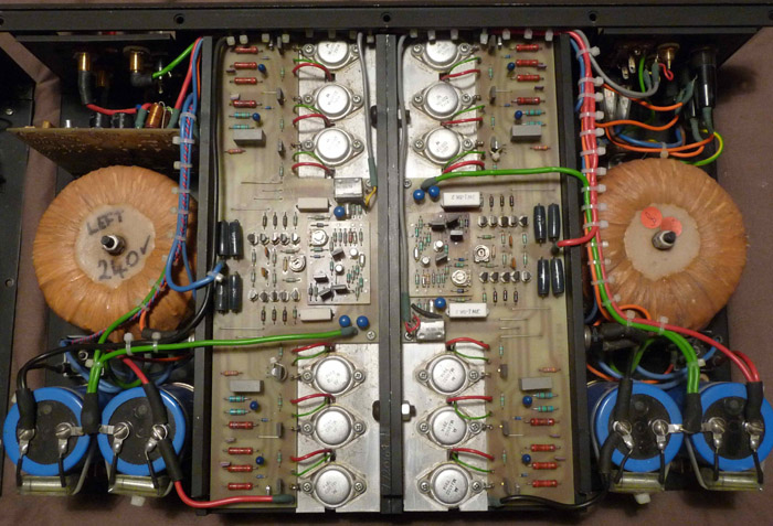 Note the massive power supplies; the massive heatsinks and the neat symmetrical layout. Note the massive power supplies; the massive heatsinks and the neat symmetrical layout.
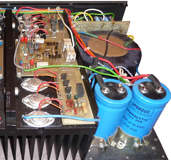 Another internal view of amplifier serial number 772079 Another internal view of amplifier serial number 772079
 The interior of the 772 Control unit showing the huge amount of wiring; the substantial power supply, again with a toroidal transformer, and the individual circuit blocks The interior of the 772 Control unit showing the huge amount of wiring; the substantial power supply, again with a toroidal transformer, and the individual circuit blocks
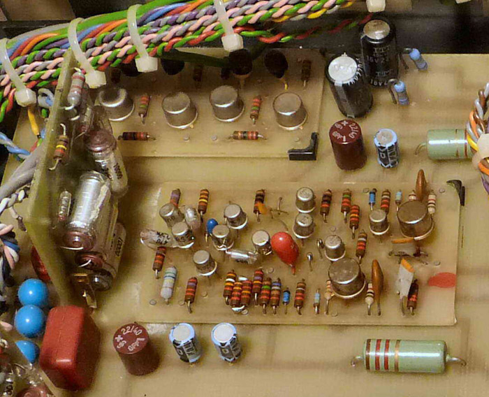 A close up of one of the circuit blocks actually a complex but super-linear amplifier stage A close up of one of the circuit blocks actually a complex but super-linear amplifier stage
Hopefully I'll dig out some circuit information when I find my original notes from 30 years ago. Many thanks to Iain Mackay who has provided many of these photographs. He has two power amps which he has named "Tirpitz" and "Bismark" in view of the battleship like construction !
|